Peak-to-peak value compressor
This one I was intending to use on an early model of the VCO I designed. The first circuit I tried out was a VCO with two op-amps I found online, basically using each op-amp as a trigger to the other, with a small delay, producing a square wave. I tried to simulate that but it wasn't really working out, so I changed it many times, until I totally revamped it. At that point I made a complicated circuit, half of which was an op-amp generating the values for the output stage to follow. Before the output stage I put this segment, so that I could make the op-amps peak-to-peak output, which was in the volts range, shrink down to the millivolt range, in order to increase the frequency. Never got the chance to try this on a breadboard either, since I scrapped that design for the one I've got on the circuits page, which I was a lot happier with. I guess it would work ok though, the idea is simple.
![]()
Import data for Circuit Simulator
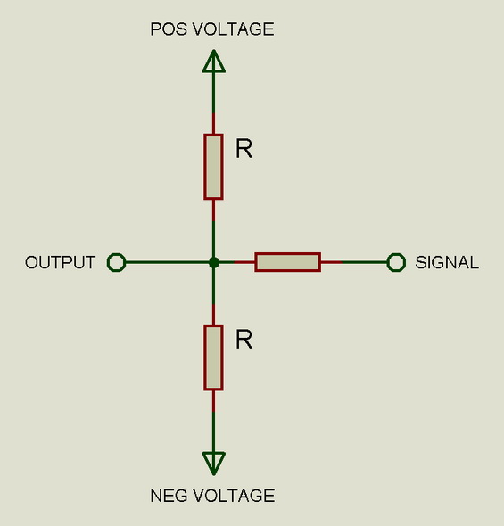
See? It's so simple I don't know why I even have a page for this circuit. Anyway, as long as the positive and negative voltages are of the same magnitude, the R resistors are the same and the resistor going from the signal terminal to the output terminal is a lot bigger than them (say, 10 times larger - depending ofcourse on how much compression you want and what the voltages are) it should work just fine. You could say its a triangle, or a voltage divider - haven't thought about it - as always, if it works, its good :)