DAC with resistors and op-amps
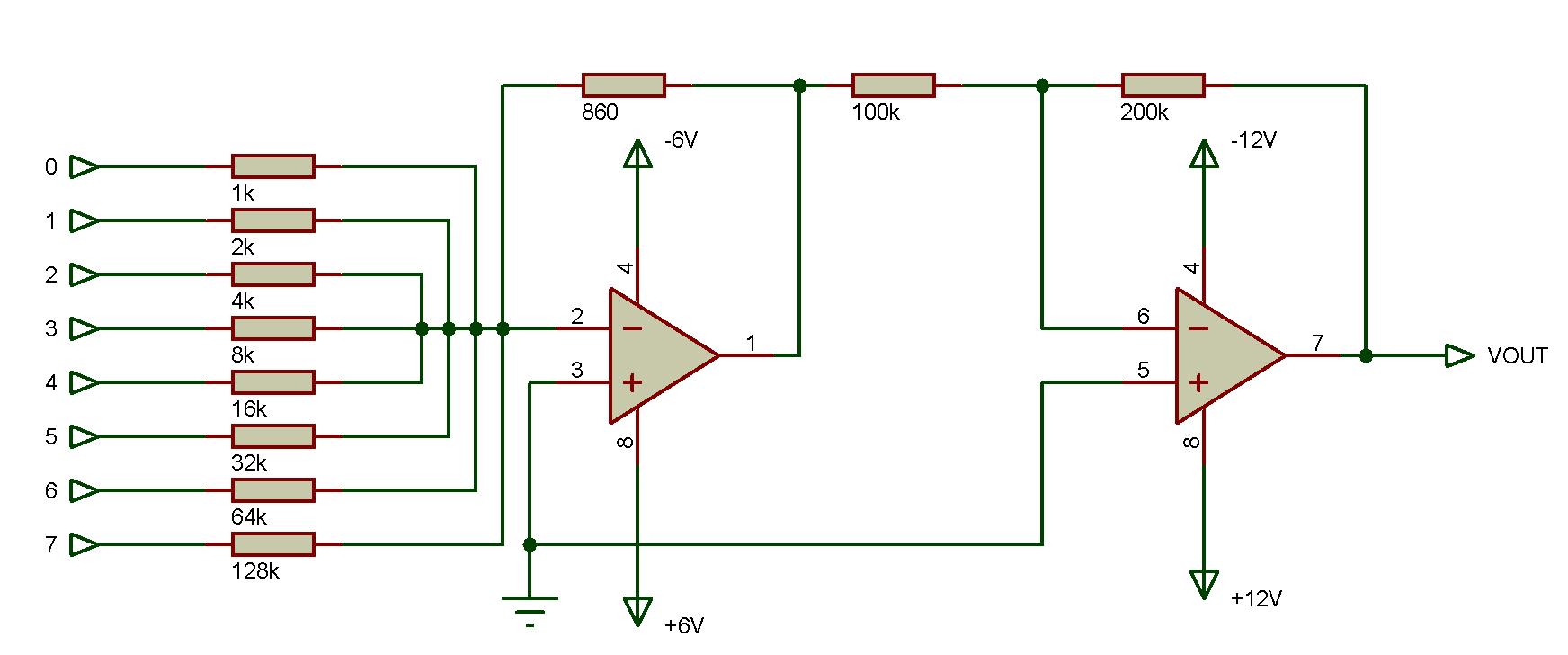
Now if you've seen the way I designed my VCO, you might remember it needed a DC voltage at its input in order to produce a steady output frequency. Since it would have to be controlled by an MCU (and since my MCUs didn't really have the DAC capabilities necessary for this, not to mention I was really afraid something would get fried...) I needed a way for the MCU to control a voltage, without having to constantly output a signal and somehow be isolated from the high voltage at the same time. So I made this array of resistors, coupled with two op-amp stages so that the MCU would have a semi-decent amount of control over the voltage level and wouldn't need to maintain it since I could just use a latch to provide a steady 8-bit value.

![]()
Import data for Circuit Simulator
Import data with E12 Series resistor values
Now, if you've tried this you might realise it's not really perfect. Specifically, the MSB doesn't really have as much influence on the output as it should. This was a tough one though - half of it I found, but I had to do a lot of fine tuning by hand in order to make it a decent 8bit-to-12V DAC. I'd like to revise this if I have time in the future, but for now, I don't need it anymore on the project, so it'll be some time for me to deal with its details.