Microcontroller pair for ROV control
When I first thought about how the ROV would control itself, I had the idea of seperating functions into ones that are simple yet need constant monitoring (the boring work) and the ones that need higher level control. So I tried to make a pair of microcontrollers connected so that they can communicate with each other directly, so that the master MCU can send commands to the slave, which will only handle motor control.
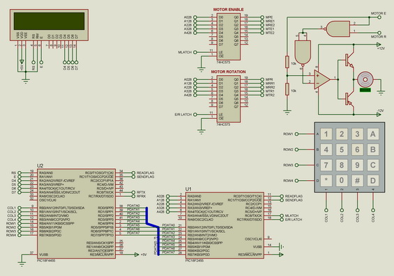
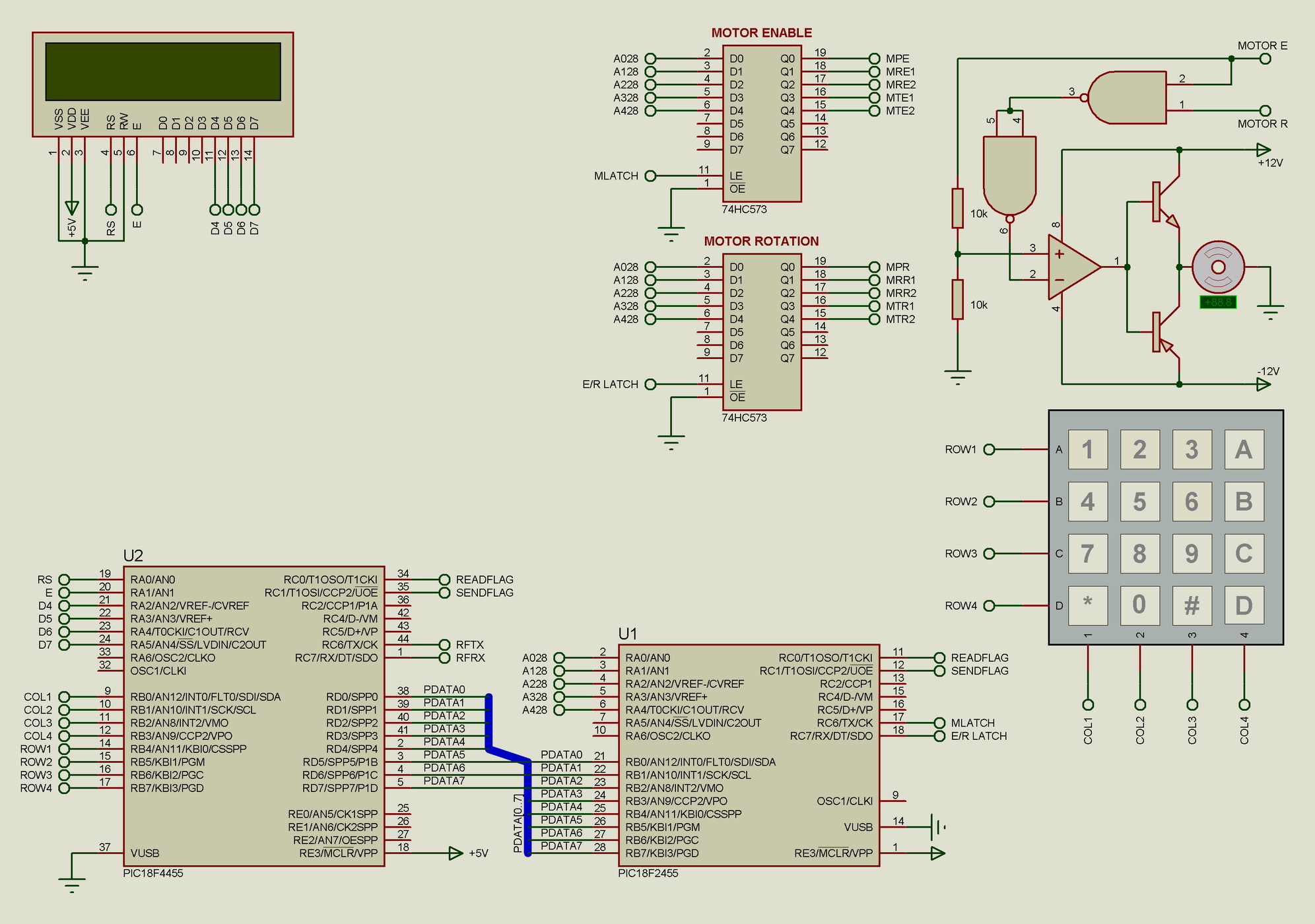
The circuit below is what came of my efforts. This is an older version, not updated with the keyboard decoder and showing only one motor control circuit for brevity. The LCD and the keyboard are there only for the demonstration - the ROV is supposed to be able to operate automatically (though, as I found out, it is MUCH harder than I thought...).
NOTE: The motor control circuit here is wrong, two resistors are missing - check the circuit from the circuits page.
If you've seen the model numbers on the MCUs, you'll notice they're PIC18 series microcontrollers. I used them here as stand-ins for the ECIO microcontrollers, which are based on the PIC18F4455 and PIC182455 accordingly for their 40pin and 28pin versions. The 28pin takes care of motor control and the 40pin is supposed to take care of everything else, giving the 28pin simple commands with directionality, speed or coordinates for it to follow. Excluding the RFTX and RFRX pins on the 40pin, everything else connected is on the diagram. Those two pins connect to the really neat RF transmitter-reciever pair I got online, which I might talk about sometime. The latches are necessary in order to save pins and they introduce a bit of extra safety into the control, since their outputs are electrically independent from the MCU.
The microcontrollers are connected through an 8-bit port and two flags, one for each MCU to signal the other when ready or to make a send request.